Classic Series Basic Valves
Job Name
–––––––––––––––––––––––––––––––––––––––––––
Contractor
––––––––––––––––––––––––––––––––––––––––––––
Job Location
–––––––––––––––––––––––––––––––––––––––––
Approval
–––––––––––––––––––––––––––––––––––––––––––––
Engineer
–––––––––––––––––––––––––––––––––––––––––––––
Contractor’s P.O. No.
––––––––––––––––––––––––––––––––––
Approval
–––––––––––––––––––––––––––––––––––––––––––––
Representative
––––––––––––––––––––––––––––––––––––––––
Viton
®
is a registered trademark of DuPont Dow Elastomers.
Watts product specifications in U.S. customary units and metric are approximate and are provided for reference only. For precise measurements,
please contact Watts Technical Service. Watts reserves the right to change or modify product design, construction, specifications, or materials with-
out prior notice and without incurring any obligation to make such changes and modifications on Watts products previously or subsequently sold.
ES-ACV-F518-F1518
Standard Materials
Body & Cover: Ductile Iron ASTM A536
Coating: NSF Listed Fusion Bonded Epoxy Lined and
Coated
Trim: 316 Stainless Steel 2" – 8" (50 – 200mm)
ASTM B62 Bronze 10" – 16" (250 – 400mm)
(Stainless Steel Optional)
Elastomers: Buna-N (standard)
EPDM (optional)
Viton
®
(optional)
Stem, Nut & Spring: Stainless Steel
Operating Pressure
Threaded = 400psi (27.6 bar)
150 Flanged = 250psi (17.2 bar)
300 Flanged = 400psi (27.6 bar)
Operating Temperature
Buna-N: 160°F (71°C) Maximum
EPDM: 300°F (140°C) Maximum
Viton
®
: 250°F (121°C) Maximum
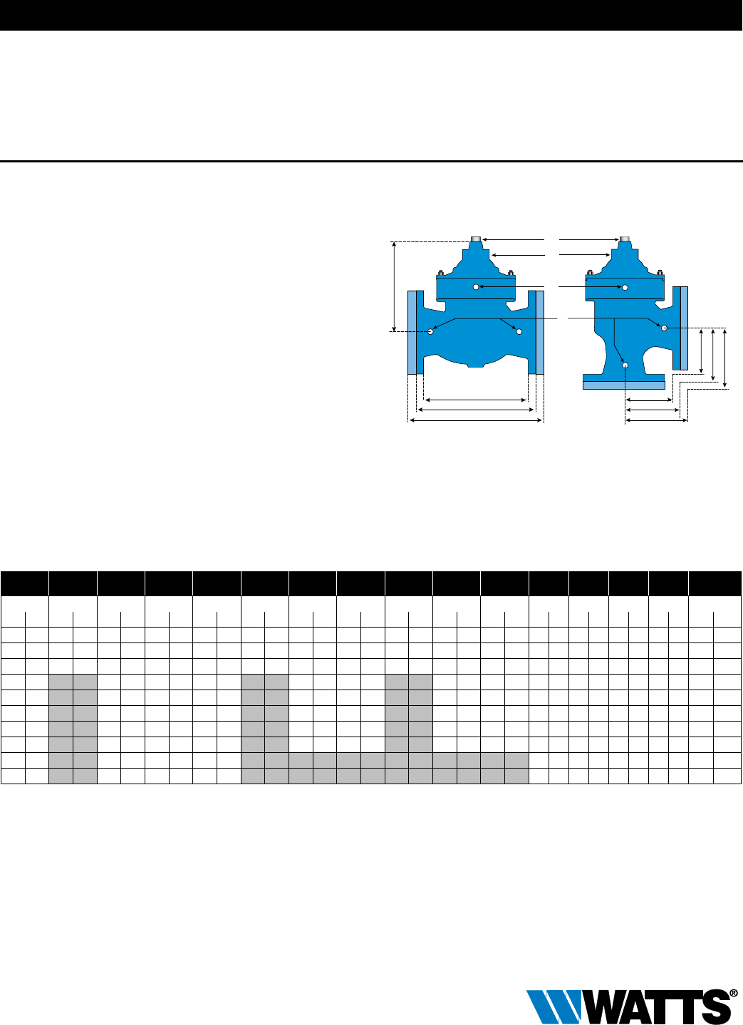
F518 (Globe) F1518 (Angle)
K
A
B
C
E
F
G
H
I
J
D
L
M
N
F518 / F1518
Full Port Ductile Iron
Dual Chamber Basic Valve with
Mechanical Check Feature
The Watts ACV Models F518 and F1518 are full port, dual
chamber basic valves that incorporate a two-piece telescoping
disc and diaphragm assembly. This assembly is the only moving
part within the valve, allowing it to open or close as commanded
by the pilot control system. The lower portion of this two-piece
assembly is a mechanical check feature, which acts indepen-
dent of diaphragm position or pilot control system, and provides
immediate check action when flow ceases.
When pressure is applied to the upper diaphragm chamber and
released from the lower diaphragm chamber, the valve travels
to a closed position. When pressure is applied to the lower dia-
phragm chamber and released from the upper diaphragm cham-
ber the valve travels to a full open position.
Model F518: Globe Pattern Dual Chamber Basic Valve with
Mechanical Check Feature.
Model F1518: Angle Pattern Dual Chamber Basic Valve with
Mechanical Check Feature.
Dimensions
Valve Size Globe
Thread
Globe 150# Globe 300# Cover To
Center
Angle
Thread
Angle 150# Angle 300# Angle
Thread
Angle 150# Angle 300# Port Size Port Size Port Size Port Size Shipping
Weights*
A B C D E F G H I J K L M N
in. mm in. mm in. mm in. mm in. mm in. mm in. mm in. mm in. mm in. mm in. mm in. mm in. mm in. mm in. mm lbs. kgs.
2 50 9
3
⁄8 238 9
3
⁄8 238 10 254 6
3
⁄8 162 4 102 4 102 4
1
⁄4 108 4 102 4 102 4
1
⁄4 108
1
⁄2 13
1
⁄2 13
1
⁄4 6
1
⁄4 6 40 18
2
1
⁄2 65 11 279 11 279 11
5
⁄8 295 8
1
⁄2 216 5
1
⁄2 140 5
1
⁄2 140 5
13
⁄16 148 4 102 4 102 4
5
⁄16 110
1
⁄2 13
1
⁄2 13
3
⁄8 10
1
⁄4 6 70 32
3 80 10
1
⁄2 267 12 305 13
1
⁄4 337 8
3
⁄4 222 5
1
⁄4 133 5
3
⁄4 146 6
1
⁄8 156 5
1
⁄4 133 5
3
⁄4 146 6
1
⁄8 156
1
⁄2 13
1
⁄2 13
3
⁄8 10
1
⁄4 6 105 48
4 100 15 381 15
5
⁄8 397 10
1
⁄4 260 6
3
⁄4 171 7
1
⁄8 181 6
3
⁄4 171 7
1
⁄8 181
1
⁄2 13
1
⁄2 13
3
⁄8 10
1
⁄4 6 230 104
6 150 20 508 21 533 14 356 8
1
⁄2 216 8
7
⁄8 225 8
1
⁄2 216 8
7
⁄8 225
1
⁄2 13
1
⁄2 13
1
⁄2 13
1
⁄2 13 375 170
8 200 25
3
⁄8 645 26
3
⁄8 670 19
1
⁄2 495 11 279 11
1
⁄2 292 11 279 11
1
⁄2 292
1
⁄2 13 1 25
1
⁄2 13
3
⁄4 19 800 363
10 250 29
3
⁄4 756 31
1
⁄8 791 22
1
⁄2 572 14
7
⁄8 378 15
5
⁄8 397 14
7
⁄8 378 15
5
⁄8 397 1 25 1 25 1 25
3
⁄4 19 1100 499
12 300 34 864 35
1
⁄2 902 24
3
⁄4 629 17 432 17
3
⁄4 451 17 432 17
3
⁄4 451 1 25 1 25 1 25 1 25 1720 780
14 350 39 991 40
1
⁄2 1029 26 660 1 25 1 25 1 25 1 25 2600 1179
16 400 41
3
⁄8 1051 43
1
⁄2 1105 30
1
⁄2 775 1 25 1 25 1 25 1 25 3300 1497
*Estimated in lbs.
 (1 pages)
 (1 pages)
 Manymanuals.com
 Manymanuals.de
 Manymanuals.fr
 Manymanuals.it
 Manymanuals.pl
 Manymanuals.cz
 Manymanuals.es
 Manymanuals-pt.com
Comments to this Manuals